Posts

Showing posts from November, 2015

Electric kettle problems and solution

Image
Electric kettle Electric kettle is a electric device which is using to heat water / tea / coffee .On market two types of kettle now . Types of kettle   There are two types of kettle in market now. Immersion Element Type Kettle. Separate Element Type Kettle. Electric kettle problems and solution Electric kettle problems and solution Problems Supply cord connected , Switch on kettle not working. When trying to switch on fuse firing. Kettle body shocking. Kettle heat control not working. Kettle base broken. Heating element fired. Connected point sparking. Supply cord connected , Switch on kettle not working. Cause Fuse fired . Circuit breaker trip . Plug not connected with cable of kettle. Supply cord problem. Switch connection  problem. Heating element terminal problem. Heating element fired.  Solution Change the fuse. On the circuit breaker. Repair plug connection Change the supply contact. Repair con...

Akai tv circuit diagrams

Image
Sharing akai tv circuit diagrams. Some popular model akai tv circuit diagram. Akai is a popular band in television world. Popular model is AkaiCT2570 Circuit diagram    CT2870 Circuit diagram   AKAI  AM-2250  Circuit diagram  AT-2250  circuit diagram.AKAI AA-1115 1125 SM. All of this circuit is SMPS. We help you to learn electronics.In our blog you can get also how to repair any thing. Mini Project of electronics and electrical. Akai tv AM-2250 and AT-2250 AKAI CT2570,AKAI CT2870 CIRCIT DIAGRAM AKAI AA 1115 AND 1125SM Circuit Diagram Please download this image of circuit diagram then watch you will get a clear circuit diagram. Share our blogs with friends.  We will get inspire for this. Thanks for visiting our blog.

Electronics door bell circuit diagram

Image
Sharing electronic door bell circuit diagram.You can make a mini project with this door bell . This electronic door bell is very simple to make.  you can make this electronics musical door bell on home. Electronic door bell circuit diagram                             Electronic door bell circuit diagram Needs to make electronic door bell circuit 3volt battery. Resistance 1  was 1k . Switch  push to on. S1 is on-off switch. Ic1  8021-2  T1 BC548 OR C8050  T2 BC557 OR C8550 LS1 4 OHMS/8 OHMS LOUDSPEAKER. Capacitor 10 micro farad 12 volt. Connect like this diagram and make your project on home. This is really good musical electronic door bell . Caution  Connect the battery with attention . Wrong connection can fired your circuit .  All points connect goodly with soldering iron and sold...

Electic iron repair problem and solution

Image
Types of electric iron There are two types of electric iron  General electric iron. Automatic electric iron. Electric iron picture.  Electric iron Types of automatic electric iron . Automatic electric iron. Automatic electric stream iron. Structure of  a simple electric iron     Electric iron structure Sole plate. Heating element. Pressure plate. Hood assembly. Supply cord.  Problem Cause and Solution to repair your electric iron Problem 1 ***Electric iron not heating .  Causes 1 :   Iron have no connection . Connection fault between terminal point and element.  Fault on plug , may be wire disconnected from plug. Heating element may be broken . Automatic iron's thermostatic switch may be not working.     Solution 1 : Check the supply cord with test lamp . Check the continuity with test lamp , if need you can open the cover and check the heating ele...

Circuit Diagram Of A Mosquito Swatter / Mosquito Racket

Image
This is a mosquito  racket which  is looking such as playing racket. But it's really a mosquito killer racket. Some of my electronics worker friend asked me to give a mosquito racket circuit. So i am uploading here in my blog. This circuit diagram of a mosquito killer/swatter is very helpful . Simple circuit diagram to know how mosquito swatter works? How mosquito swatter works ? This is a simple diagram which showing how mosquito swatter/ Mosquito racket works ? For descriptive circuit diagram of mosquito racket check bellow. Mosquito swatter step up transformer Mosquito rackets Transformer S1-F2 - Primary have 3t 0.4mm ENCU S2-F2 Primary have 3t 0.4mm ENCU S3-F3 Secondary have 360t 0.25mm ENCU Actually this is a step up transformer which is supplying a high voltage .It's converting voltage dc to ac. Descriptive Circuit diagram of a mosquito killer or mosquito swatter Circuit diagram of a mosquito racket bat This is a full circuit diagr...

how to fix a heater ?

Image
Electric Heater Problems   Supply cord connected , When trying to switch ON heater is not working. Fuse firing when trying to switch ON. Heater's body shocking. Heater heating level out of control. Base plate broken of heater. Heating element wasted. Connected point sparking. Table Heater Room Heater Immersion heater   Electric heater problems,cause and solution . Problem  Supply cord connected switch is also ON but heater is not working. Causes  Fuse fired. Circuit breaker trip. Plug is not connected with socket twisty . Switch disconnected. Heating element terminal disconnected. Heating element short circuit. Solution Change the fuse. On the circuit breaker again. Check the socket contact with plug. Check supply cord it can be dropped or short. Check the connection with switch. Change the heating element.   Problem  Fuse firing when trying to switch ON.   Causes  ...

dryer not heating?get solution

Image
My Hair Dryer Is Not Heating Your Solution Is Here.  Electric hair dryer is a domestic appliance which is drying your hair.But your hair dryer is not heating it's a problem. You can get solution here in my electrical blog. Hair Dryer Structure of electric hair dryer   Switch  Handle  Body Air filter Safety net Motor  Fan Heating Element Supply Cord   Necessary Points Of Hair Dryer    Switch  On qualified hair dryer companies using many types of switch . Cool shot switch   - This is a push switch when you push switch once it will on . Heat switch    -  This is a sliding switch . Speed switch - This is a sliding switch also. Problems Of Hair Dryer : Supply cord is connected . When i am switching hair dryer is not running. When trying to on switch on fuse instant fusing. It's not working when switching one time i need two or three times to run hair dryer. When h...

types of relay

Image
What is Relay ? Relay is a automatic electronics components which is inserted on circuit breaker and power circuit. If relay found any problems on circuit ,Relay gives helps circuit breaker to close the power of circuit. That's why we called circuit breaker  security of power. Types of relay Types Of Relay There are many types of relay I am describing types of relay Structure basis types of relay  Electromagnetic Type relay Electro-Dynamometer Type Relay Induction type relay Electronic type relay Thermal Type Relay Polarized Type Work basis types of relay Current Relay Voltage Relay Power Relay Frequency Relay Phase Unbalance Relay Power Factor Relay Impedance Relay Timing Types of relay Instantaneous Relay Definite Time Relay Inverse Type Current Definite Minimum Time Lag Relay   Use of relay  To rescue from short circuit of transmission and distribution . To get rescue from transformer...

how to make an audio amplifier ?

Image
Learning How to make an audio amplifier . This is a qualified audio amplifier circuits . I will discuss here step by step you can get all this elements on your near electronics market so it's too simple .Let's start. how to make an audio amplifier ? Step 1  :  Collect some elements to make this audio amplifier . 12V-0-12V 3A Or  3000MA Transformer . Electrolyte capacitor 35V 3300mfd. Rectifier Diode 1N4007 2 pieces.  LA4508 audio circuit board. Base tone control circuit with 4 volumes. Now look at the picture bellow given.And connect like this i have linked. 12v transformer Electrolyte capacitor 35V 3300mfd. Diode 1N4007 LA4508 audio amplifier circuits Base tone control circuit with 4 volumes. Step 2  Make Ct connect of rectifier diode . Capacitor have two legs  one is positive and one is negative . which side have - sign mean negative sign this leg is negative. Now others one is positive. Make a connection...

12v battery charger circuit you can make it.

Image
12v battery charger circuit I will share  12v battery charger circuit / 9v battery charger circuit  ,  6 V battery charger circuit. You can make this on home . It's very simple to make 12v battery charger circuits.We are helping you to learn basic electronics . Needs to make 12v battery charger circuit Step down transfer 12v   D piece diode 1N4007   Circuit to make 12v battery charger circuit  This is a hand art circuit  so if you fetch any problem just knock me on comments. 12v battery charger circuit Extension  you can also use a  electrolyte capacitor for quick charge    25 volt 1000 micro farad . Share our post it will help us to get good results.  

Lg TV Circuit Diagram

Image
Welcome to Our  Electronics Blog Lg TV Circuit Diagram I will share some lg tv circuit diagram here . Most popular lg tv circuit is LG CF20F - SCHEMATIC ,   LG CB775BN , TV set LG PC 53A . So we are sharing the diagram of this all circuits . Lg TV is a most popular brand TV in many country. When some one  searching for lg TV circuit diagram just ask me in comments i will try to manage. Diagram of lg CRT TV  Lg crt tv circuit diagrams    This is a perfect diagrams of lg crt tv . You can download this picture . And repair lg televisions.  Goldstar pc-53a chassis Diagram                                                                  Goldstar pc-53a chassis Diagram Lg cb775bn Circuit diagrams. Lg cb775bn Circuit diagrams.  

Bridge Rectifier Circuit | What Is Rectifier Circuit ?

Image
Learn Bridge Rectifier Circuit | What is rectifier circuit ? What is rectifier ? Rectifier is a electronics component. Which is converting power  AC (Alternative Current ) to  DC   (Direct Current). Basically we are using diode as a rectifier . Rectifier mainly using the diode to make follow current in only one direction . Bridge rectifier circuit is bellow given. Types of rectifier   They are two types of rectifier circuit .One is Half wave rectifier circuit   second is full wave rectifier circuit / bridge rectifier circuit . Half wave rectifier circuit  This is very simple rectifier circuit . We are using single diode to make this type rectifier circuit . As output getting just half cycle of wave  and efficiency is half. Voltage is too high  and it's easy to make cheap also. Half wave rectifier circuit diagram Half wave rectifier circuits Full wave rectifier circuit / Bridge rectifier circ...

Star Delta Connection Diagram and Star Delta Starter Wiring Diagram

Image
On this lesson learning about , 3 phase induction motor star delta connection and showing star delta connection diagram Star Delta Starter Wiring Diagram Star delta connection is a program of 3 phase induction motors. On there in this post i show you Star Delta Starter Wiring Diagram and Star Delta Connection Diagram So no waiting uploading the diagram there. Star connection diagram Star connection looking like as Y . delta motor connection diagram star delta connection diagram Thank you stay with us to know more electronics tutorial.

We will help you to learn electronics quickly from our this blog. Read Care fully!!!!

We will help you to learn electronics quickly from our this blog. So don't wait follow our blog. We will not take a benefit also from you .. It's free really we want to just help you about electrical and electronics.I am a electrical engineer and worked on electronics and electrical. So i want to help you about electronics learning and electrical learning.    Why i have to learn electronics?  Electronics is a very useful and  important subject on real life. Learn electronics for your own necessary work on your real life.You will not asked for a payment.This is free totally free learning about electronics and bonus is electric.Don't wait follow our blog. We will post electric diagram , electronics diagram , Simple electronics parts information , To make simple electronics project ,Don't wait follow us .. Our Blog   Learn electrical and electronics. Very easy to learn electronics , because you can learn it from home. If you have only ...

How to check a electric capacitor | Is your capacitor in good position or dead .

Image
Hey  sharing How to check a electric capacitor | Is your capacitor in good position or dead . Basics  Mainly a capacitor have two legs.Electric capacitor using on fan and  motor. Some times your fan or motor running on low speed . Then you have to check first the capacitor. The capacitor is dead or good . Some capacitors Electric capacitor testing Then how can you check your capacitor ? Mainly you need a series tester .First collect series connection.Or you can make a series connection also with a Bulb series with a 2 pin socket. Then supply power on this series board.Now connect capacitor with 2pin socket.And hold it for 10 second then remove capacitor and shot this 2pin of capacitor with wire . It's will make a spark . If this spark is too noisy then your capacitor is okay . If low spark  then your capacitor dead .You have to change this capacitor.There are many type of capacitor usually we are using on fan . 2.5uF / 3.5uF . ...

How to make a decorating light?

Image
Making a decorator light Decorating light is a type of light. Which is using  to decorate any home office room  and any celebration center. It's very good elements to calibrate Christmas,Halloween,Eid,Puja Etc. How it made? Mainly it made by some LED ( Light Emitting Diod ) . Some series connection  added some led statistically . You can get LED on any electronics shop. Added statistically 150 to 200 LED . Let's make decorating light. Need's to make decorating light Resistance R1 = 27 Kilo Ohms   Resistance R2 = 27 Killo Ohms Polarist C apacitor C1 = 100uF 10V Polarist C apacitor C2 = 100uF 10V  Non Polarist Capacitor C3 = 203 or 104. Transistor Q1 = 9014 Transistor Q2 = 9014 6 Piece red led 6 piece blue or any color LED . House wearing plastic channel . Connect the circuit like as this diagram i have gave bellow. Diagram to make decorating light Set Led on plastic channel like as bellow photo . And  set all led as ...

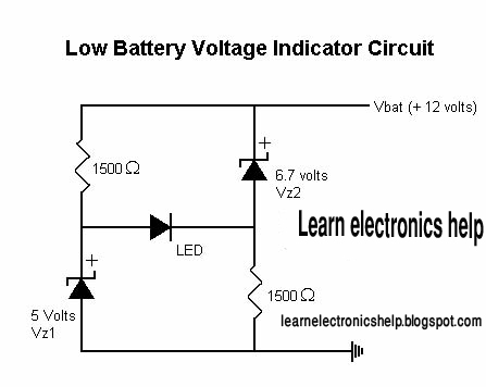
How to make a low battery indicator circuit ?Low battery indicator Schematic

Image
On this lesson i am going to share how to Make a  low battery indicator circuit Low battery voltage indicator is a very simple electronics devices.With this you will get signal that your battery having with low charge.This low battery indicator circuit is too simple to make. Needs some elements only to make this indicator circuit.You will get this all elements on near electronics market and this all elements is too much low rates.I gave there a good diagram to make this circuit easily. low battery indicator schematic You will get a signal when battery is low.You can directly measure the level of 12 volt battery How to make a low battery voltage indicator circuit